
Digging through some old papers I came across some of the circuit diagrams (or schematics if you're from across the pond) I drew for some of the FM and AM transmitters and audio processors I employed many years ago. Most of the diagrams date back to the late 1980's or early 1990's. Click on any of the images to get the full-size version.
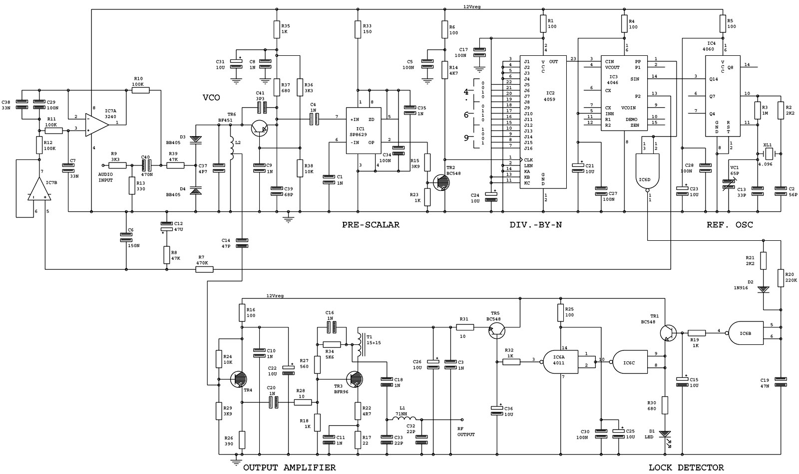
This is a much played with and optimised design for an 88-108 MHz synthesiser, programmable in 25 kHz steps. It produces about 50 mW output (and thus feeds nicely into the amplifier shown below) with no tuning required other than to set the inputs of the divide-by-N counter to the wanted frequency.
FM modulation is achieved just by injecting audio on the audio input (audio response is pretty flat from 10 Hz to over 200 kHz so can be used for stereo and RDS). This versatile design has also been used for link transmitters at around 48, 52 and 200 MHz with a few changes in the VCO and output filter, and by changing the reference crystal you can alter the channel spacing too. The power output is switched off until the synthesiser achieves lock to prevent transmissions on the wrong frequency (which can be disasterous if you've amplified it to high power and got it connected to a highly resonant antenna).
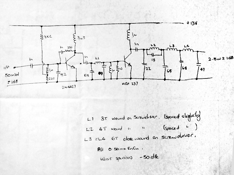
Here's a nice design for a 2.5 Watt power amplifier for the FM band. An input of 50 mW gives a final output power of 2.5 Watts with a 13 Volt supply. The best bit is that the amplifier requires no tuning once it's built - it gives roughly the same gain and output power right across the FM band from 88 to 108 MHz. There's even some hefty output low pass filtering to make sure that harmonic output is small and no interference is caused to users (mostly military!) on multiples of the FM frequency being amplified. A nice design based on, believe it or not, a military one...!
This AM transmitter provides a nice, clean output of about 1 Watt (carrier power). Though designed for the medium wave band (circa 1.5 MHz) it would work equally well on higher frequencies (6.2 MHz for example) with a few tweaks in component values (see table on left - C15 should be adjusted for maximum output).
| Frequency | C10 | C7&C8 | L1 |
|---|---|---|---|
| 1.6 MHz | 1.5 nF | 2.7 nF | 5.7 µH |
| 3.9 MHz | 270 pF | 1 nf | 2.3 µH |
| 6.2 MHz | 100 pF | 680 pf | 1.5 µH |
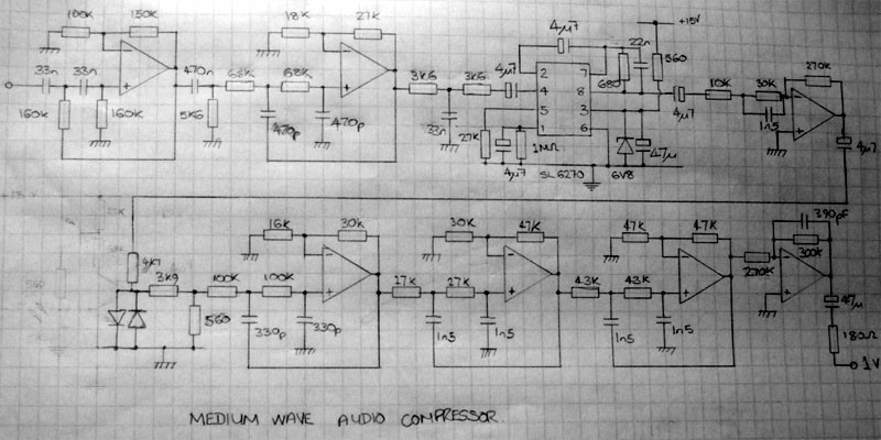
My first attempt at an improved audio processor for GCR using a Plessey SL-6270 VOGAD (VOice controlled Gain Adjusting Device) which is designed more for PMR use than broadcast use but with the right parameters does a reasonable job. It deals with a massive dynamic range of inputs (about 60dB) which does tend to mean that if you don't set it up properly you can hear every tiny background noise in the studio. There's a bit of low and high-pass filtering on the input to avoid unwanted frequencies causing the compressor to 'pump'. There's also a lovely 7-pole Chebyshev low-pass filter on the output with a cut-off at about 6 kHz. All the op-amps are TL072 or TL074. Watch out for the difference between the 'earth' symbol and the 'ground' symbol as one relates to 0V and the other to mid-rail (typical supply voltage is 15V).
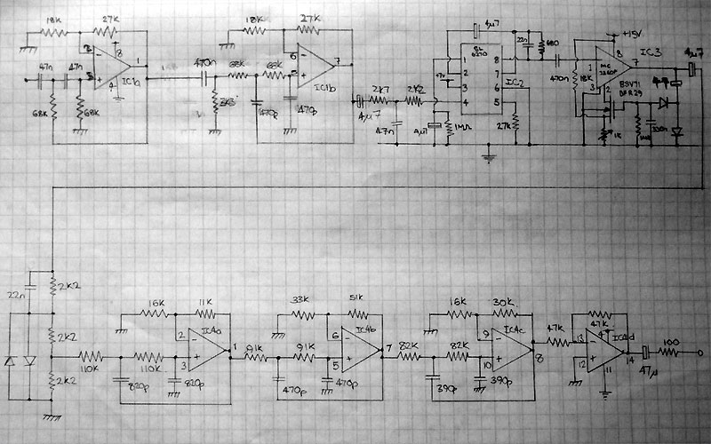
The Mark 2 version of the processor above. Now with an added limiter after the compressor (based around an MC3340 and a rather odd BSV71/BFR29 I.G.F.E.T.). A new 6-pole output low-pass filter to provide a tight fit to the transmitter specifications allowed at the time for closed-loop AM radio stations. There's a bit more HF boost (or pre-emphasis) before the clipper on this version to give the audio a more 'lively' feel. This design was in use at GCR for about 2 years until my super 3-band processor took over. Same precautions over the diagram as above apply and op-amps are also TL072 or TL072.
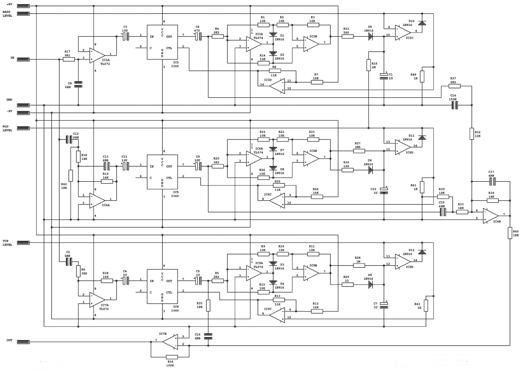
The Mark 3 version got massively more sophisticated (and better sounding). This diagram is for the heart of the processor. It's a 3 band audio processor/limiter/compressor (call it what you will) with a few special features: (1) The decay on the bass compressor is tied in to the mid compressor which gives a much more balanced sound, and (2) there are cross-overs before and after each compressor, thereby reducing any distortion produced. The resulting sound is very loud and very impressive. The 3 audio bands compressed are 0-250 Hz, 250-1300 Hz and 1300-6500 Hz. The +/- 8V supply is quite critical as it sets the threshold for compression to the MC3340 chips. There's still a transmitter kicking around with this processor in it - if I can get my hands on it I'll record some output.
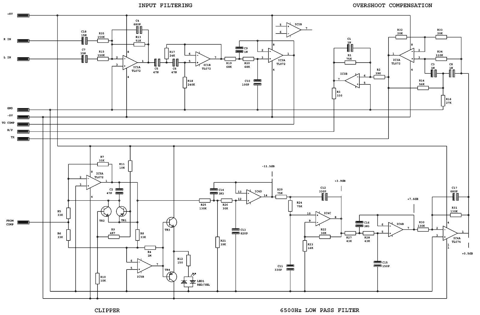
This is the second half of the Mark 3 diagram and shows the input high and low-pass filtering; the clipper (with a snazzy LED to show when clipping is occuring); and a new and even better output 6.5 kHz low-pass filter together with a phase corrector to provide overshoot compensation (and therefore allow the transmitter to be driven harder).
The frequency response of the output filter is flat to 6 kHz, -3dB @ 6.5 kHz, -23dB @ 7.6 kHz and -40dB @ 9 kHz, which fits exactly the allowed response for closed-loop AM stations for which it was designed. Without the overshoot compensator, the filter has an overshoot of around 2.6 dB; with it, overshoot is virtually nothing - thereby giving a 2.6dB increase in loudness. All components (including the capacitors) need to be 1% tolerance for this circuit to work properly.
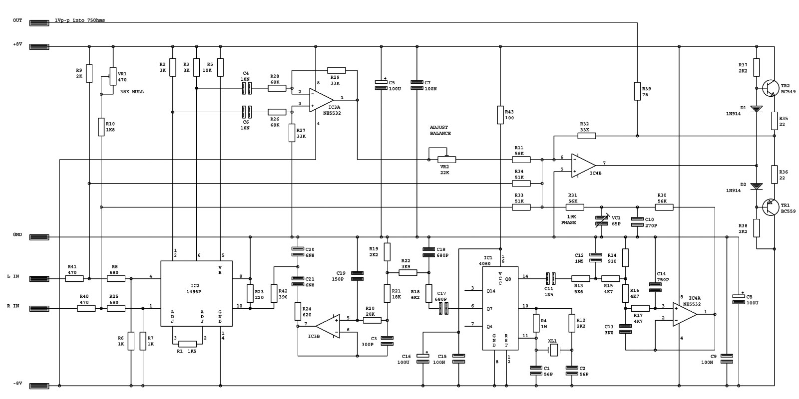
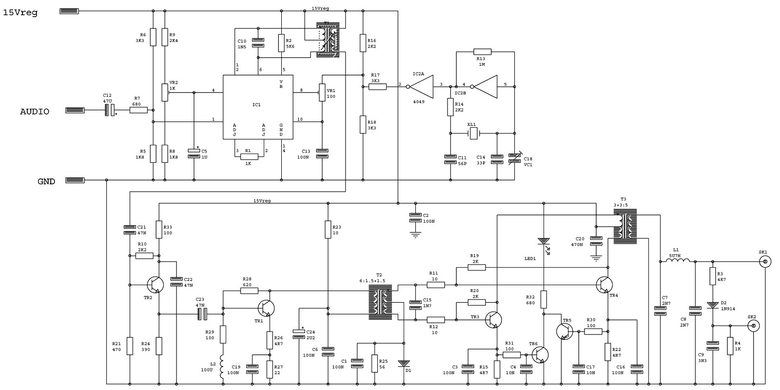
After many years of fiddling around with various designs for stereo encoders I finally settled on this design. It produces a very clean signal with good separation (it performed as well as any other encoder I tested, which included some expensive professional ones) and has been used on many professional commercial radio stations. There's no input filtering on it so it has to be proceeded by a 15 kHz low-pass filter (which was something I put on my processor instead of on the encoder). It needs a +/- 8 Volt supply but +/- 9V would work equally well and it produces 1 Volt peak-to-peak into a 75 Ohm load (and a bit more into a high impedance one) with 0dBu audio drive. XL1 should be a 4.864 MHz one.
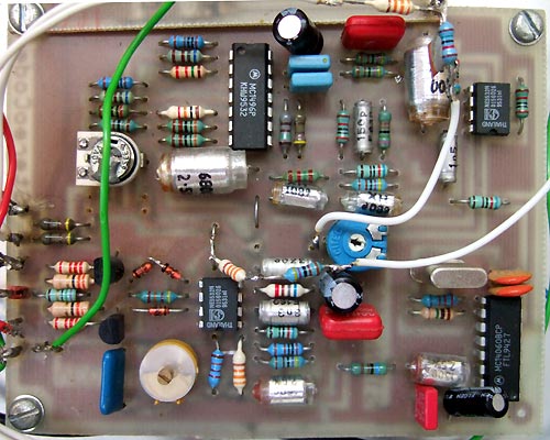
The wires and extra PCB (off the top of the shot) in the picture are for a composite clipper that was added afterwards, which provides about another dB and a half of loudness.
Disclaimer: The information contained on this web-site is presented for your enlightenment, education and entertainment only. We do not condone unlicensed broadcasting or any illegal use of the radio spectrum, nor is there any intention on our part to incite or glamorise such activities.
[ This page last updated Mon 30 Jan, 2017. Viewed 3 times. Last viewed Tue 15 Apr, 2025 at 01:13 ]